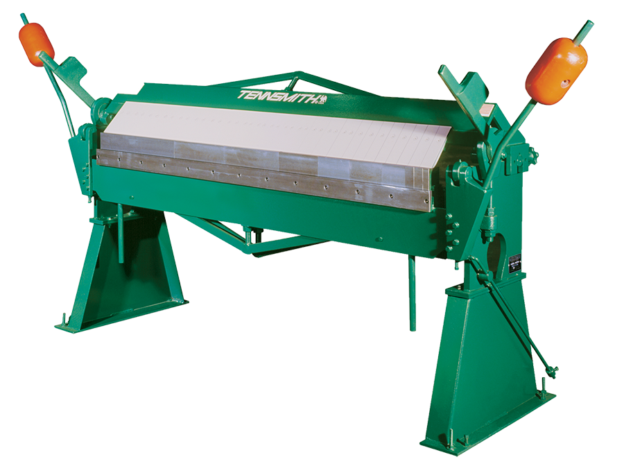
|
HBT48-12 |
HBT72-16 |
EBT60-16 |
| Capacity, Mild Steel |
12 Gauge
2.7 mm |
16 Gauge
1.6 mm |
16 Gauge
1.6 mm |
| Capacity, with Bending Support Angle Removed, Mild Steel |
16 Gauge
1.6 mm |
20 Gauge
1.0 mm |
|
| Bending Length |
48 in.
1220 mm |
72 in.
1828.8 mm |
60-1/4 in.
1537 mm |
| Maximum Lift Of Beam |
1-1/2 in.
38.1 mm |
1-1/2 in.
38.1 mm |
4 in.
102 mm |
| Front To Rear Beam Adjustment |
1/2 in.
13 mm |
1/2 in.
13 mm |
1 in.
25 mm |
| Maximum Depth Of Box |
4 in.
101.6 mm |
4 in.
101.6 mm |
4-1/8 in.
105 mm |
| Minimum Reverse Bend |
5/8 in.
16 mm |
5/8 in.
16 mm |
5/8 in.
16 mm |
| Minimum Flange In Capacity Material |
1 in.
25 mm |
1 in.
25 mm |
|
| Top Segment Tooling Widths |
2, 3, 4 in.
50.8, 76.2, 101.6 mm |
2, 3, 4 in.
50.8, 76.2, 101.6 mm |
|
| Lower Segment Tooling Widths |
1, 1-1/2, 4, 6, 8, 12, 20 in.
25, 38, 102, 152, 203, 305, 508 mm |
1, 1-1/2, 4, 6, 8, 12, 20 in.
25, 38, 102, 152, 203, 305, 508 mm |
1, 1-1/2, 4, 6, 8, 12, 20 in.
25, 38, 102, 152, 203, 305, 508 mm |
| Bending Beam Tooling Segments |
1, 1-1/2, 6, 8, 12, 20 in.
25, 38, 152, 203, 305, 508 mm |
1, 1-1/2, 4, 6, 8, 12, 20 in.
25, 38, 102, 152, 203, 305, 508 mm |
|
| Maximum Transverse Bend (through tooling centers) |
2 in.
50.8 mm |
2 in.
50.8 mm |
2-1/4 in.
57 mm |
| Maximum Transverse Bend (at either end of machine) |
3 in.
76.2 mm |
3 in.
76.2 mm |
|
| Dimensions (counterweights in place) |
72 x 36 x 53 in.
1829 x 915 x 1346 mm |
89-1/2 x 36 x 53 in.
2273 x 915 x 1346 mm |
72 x 45-1/2 x 31-1/2 in.
1829 x 1156 x 800 mm |
| Shipping Weight |
1750 lbs.
795 kg |
2200 lbs.
1000 kg |
1150 lbs.
521.6 kg |


